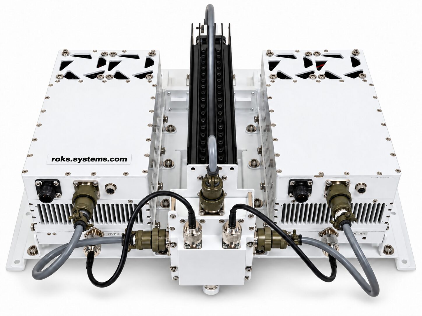
The Automatic 1+1 Outdoor Ku-Band BUC Redundancy System maintains satellite uplink operation by selecting a primary BUC and switching to the secondary unit if a fault is detected. Each BUC accepts 950-1750 MHz input, uses a 9750 MHz LO, and provides 10700-11500 MHz output with 46 dBm Psat, 43 dBm Plinear, and 72 dB typical gain.
Monitoring and control are available through an Ethernet web interface and serial RS-485. The system also provides 1 dB gain adjustment, LED status indication, easy replacement of a failed BUC during operation, and an optional 10 MHz reference generator. System dimensions are 650 x 400 x 300 mm, with weight up to 11 kg.
Technical Specifications of the Automatic 1+1 Outdoor Ku-Band BUC Redundancy System
The single BUC input interface operates from 950 to 1750 MHz, with 50 Ohm impedance, maximum input VSWR of 1.5, and an N-type female connector.
The internal local oscillator frequency is 9750 MHz. Specified LO phase noise is -75 dBc/Hz at 1 kHz, -85 dBc/Hz at 10 kHz, and -95 dBc/Hz at 100 kHz.
The BUC output covers 10700-11500 MHz. Output power is specified as 46 dBm Psat and 43 dBm Plinear, with 72 dB typical gain. IMD3 is specified as -25 dBc maximum for two signals spaced 5 MHz apart at Plinear.
Frequency-response performance includes ±2 dB flatness over the full band, corresponding to 4 dB peak-to-peak maximum, and 0.5 dB peak-to-peak gain flatness over 40 MHz.
Spurious characteristics are specified as -55 dBc maximum in-band at P1dB, -60 dBc maximum out-of-band, -40 dBm maximum LO leakage, and 60 dB minimum image rejection.
The system operates from a 30-60 VDC supply, with 36 VDC nominal input voltage, and maximum specified power consumption is less than 220 W.
Key Features of the Automatic 1+1 Outdoor BUC Redundancy System 10.7-11.5 GHz
- Automatic 1+1 redundancy.
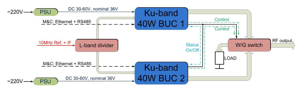
The system automatically selects a Primary BUC and maintains a second BUC as the redundant unit.
- Automatic fault detection and waveguide switching.
When a fault is detected in the Primary BUC, the system automatically switches to the Secondary BUC through the waveguide switch.
- Continuous Primary BUC supervision.
The Secondary BUC continuously checks the operating status of the Primary BUC for faults.
- Ethernet web-interface monitoring and control.
The system supports remote M&C through a web interface using Ethernet.
- RS-485 control.
Monitoring and control are also available through a dedicated control program using serial RS-485.
- 1 dB BUC gain control.
BUC gain can be adjusted in 1 dB steps.
- Clear LED status indication.
The BUC status is displayed using LEDs: Green – OK, Blink Yellow – MUTE, Red – Alarm.
- Replacement during system operation.
A failed BUC can be replaced while the redundancy system remains operational.
- Optional 10 MHz reference generator.
A 10 MHz reference generator is available as an optional system feature.
- Mounting and connection accessories.
The system includes a mounting kit and connection cables.
Applications
The Automatic 1+1 Outdoor Ku-Band BUC Redundancy System is intended for RF systems where automatic BUC backup and continuous operation are required.
- Ku-band satellite uplink systems.
The 10700-11500 MHz output range and 950-1750 MHz input range support Ku-band BUC operation.
- Outdoor BUC installations requiring redundancy.
The system provides two BUC units with automatic Primary/Secondary management.
- Systems requiring automatic fault recovery.
Automatic BUC fault detection and waveguide switching allow the secondary unit to take over when a Primary BUC fault is detected.
- Remotely monitored RF installations.
Ethernet web M&C and RS-485 control allow the operating status and BUC settings to be managed through the available control interfaces.
Compatibility of the Automatic 1+1 Outdoor Ku-Band BUC Redundancy System GaN 72 dB Gain
The system is intended for configurations requiring 950-1750 MHz IF input, 10700-11500 MHz RF output, N-type female IF connection, and 30-60 VDC power. The supplied data specify WR75-G for the single BUC output interface and WR137-G for the redundancy system RF output connector. Ethernet and RS-485 are available for monitoring and control.
How It Works ❓
- Automatic Primary BUC selection.
When the system operates, one BUC is selected as the Primary unit. After a complete OFF/ON cycle, the Primary BUC may be selected automatically and may change.
- Continuous fault monitoring.
The Secondary BUC continuously monitors the status of the Primary BUC.
- Automatic failover.
If a Primary BUC fault is detected, the system automatically changes the RF path to the Secondary BUC through the waveguide switch.
- Frequency conversion.
Each BUC receives a signal within 950-1750 MHz, uses the 9750 MHz local oscillator, and generates an output within 10700-11500 MHz.
- Remote monitoring and gain control.
System operation can be monitored and controlled through Ethernet or RS-485, while BUC gain is adjustable in 1 dB steps.
- Service without stopping the complete redundancy system.
A failed BUC can be replaced while the system remains in operation.
Why Choose the Automatic 1+1 Ku-Band BUC Redundancy System 46 dBm Psat❓
The Automatic 1+1 Outdoor Ku-Band BUC Redundancy System combines automatic Primary/Secondary BUC selection, fault detection, waveguide failover, 46 dBm GaN Psat output power, 72 dB typical gain, Ethernet and RS-485 monitoring, 1 dB gain adjustment, and replacement of a failed BUC during operation. Its defined RF characteristics, remote M&C capabilities, and integrated redundancy functions provide a complete solution for systems where uninterrupted BUC operation is required.
Order on our website today – get your personal discount 🤝
Any questions? Ask our manager – we are always glad to help select the exact parameters according to your telecommunication needs 📞