The X-band LNB 7.7–8.25 GHz WR-112 N/F/SMA is engineered for high-precision RF applications such as radar, telemetry, and X-band satellite ground stations. It downconverts signals in the 7.7–8.25 GHz band to a 950–1500 MHz intermediate frequency, using a 6.75 GHz PLL-stabilized local oscillator with ±5/10/25 kHz LO stability.
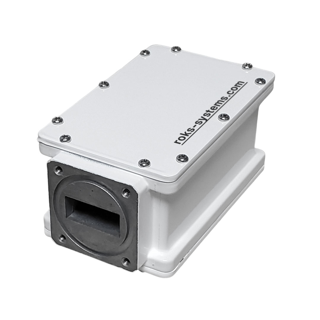
Designed with a WR-112 waveguide flange (with groove), the LNB provides outstanding performance in real-world environments. Its typical 0.6 dB noise figure, 60 dB gain, and excellent phase noise characteristics make it a trusted solution for demanding applications. The LNB comes in a compact, IP67-rated waterproof housing, and supports +12 to +24 VDC power input.
L.O.: 6.75 GHz IN freq.: 7.7-8.25 GHz OUT freq.: 950-1500 MHz
⭐ Key Features:
Input: 7.7–8.25 GHz (X-band)
Output: 950–1500 MHz (IF)
Local Oscillator: 6.75 GHz
Noise Figure: 0.6 dB typ / 0.7 dB max
Conversion Gain: 60 dB typ (55–65 dB range)
Gain Flatness: ≤4 dBp-p, ≤1 dBp-p per 36 MHz
Output P1dB: +5 dBm min
Image Rejection: ≥40 dBc
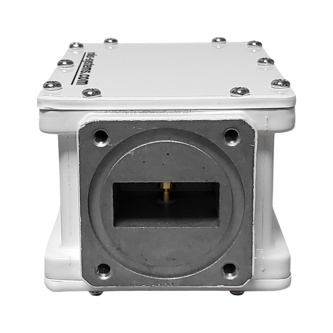
WR-112 waveguide input with groove
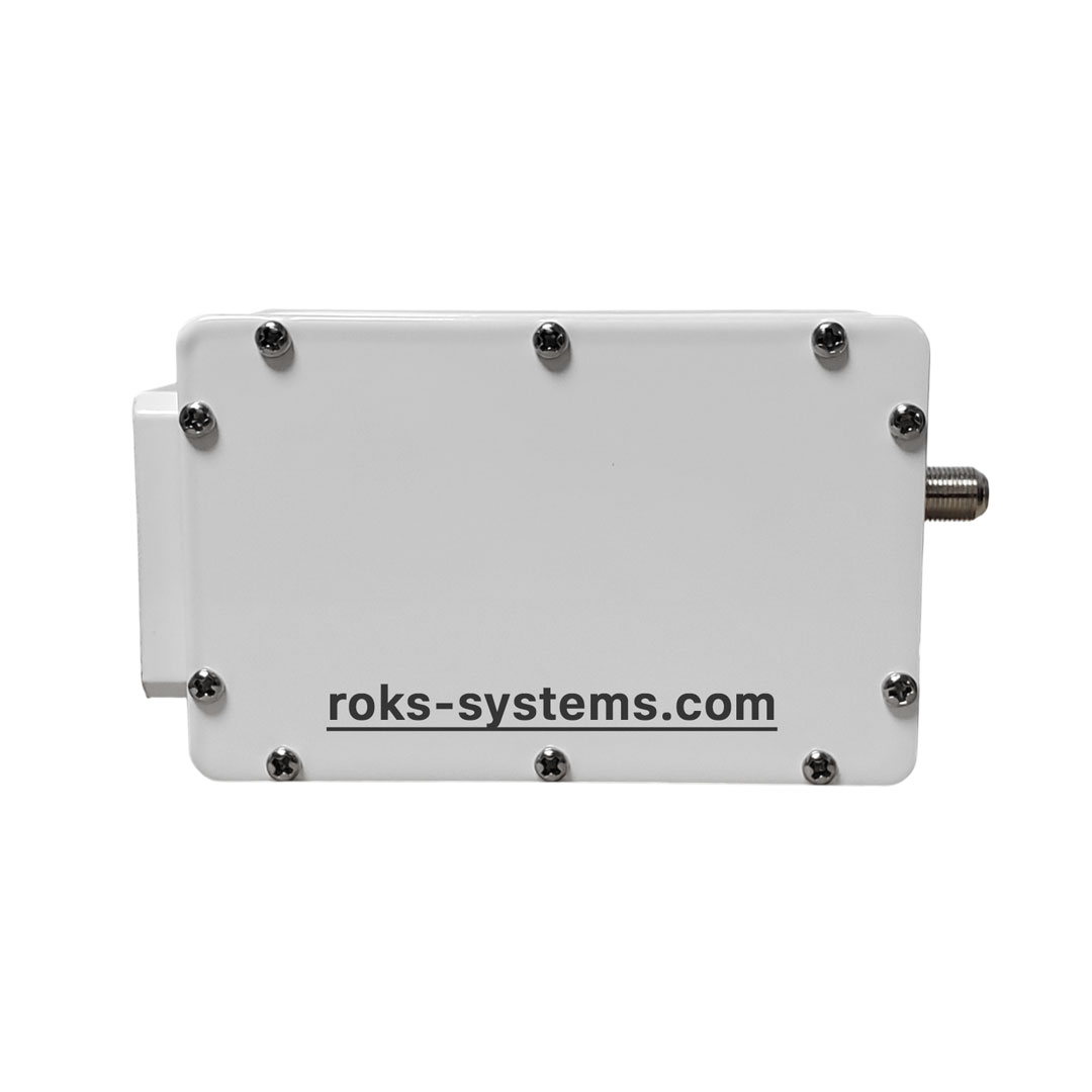
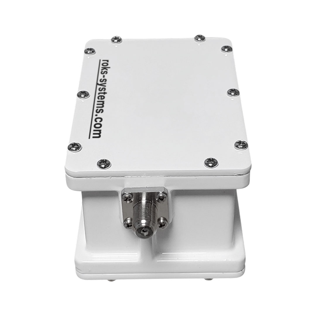
F-type or N-type output connectors
Power: +12 to +24 VDC, 300 mA max
Waterproof: IP67
Operating Temp: –40°C to +60°C
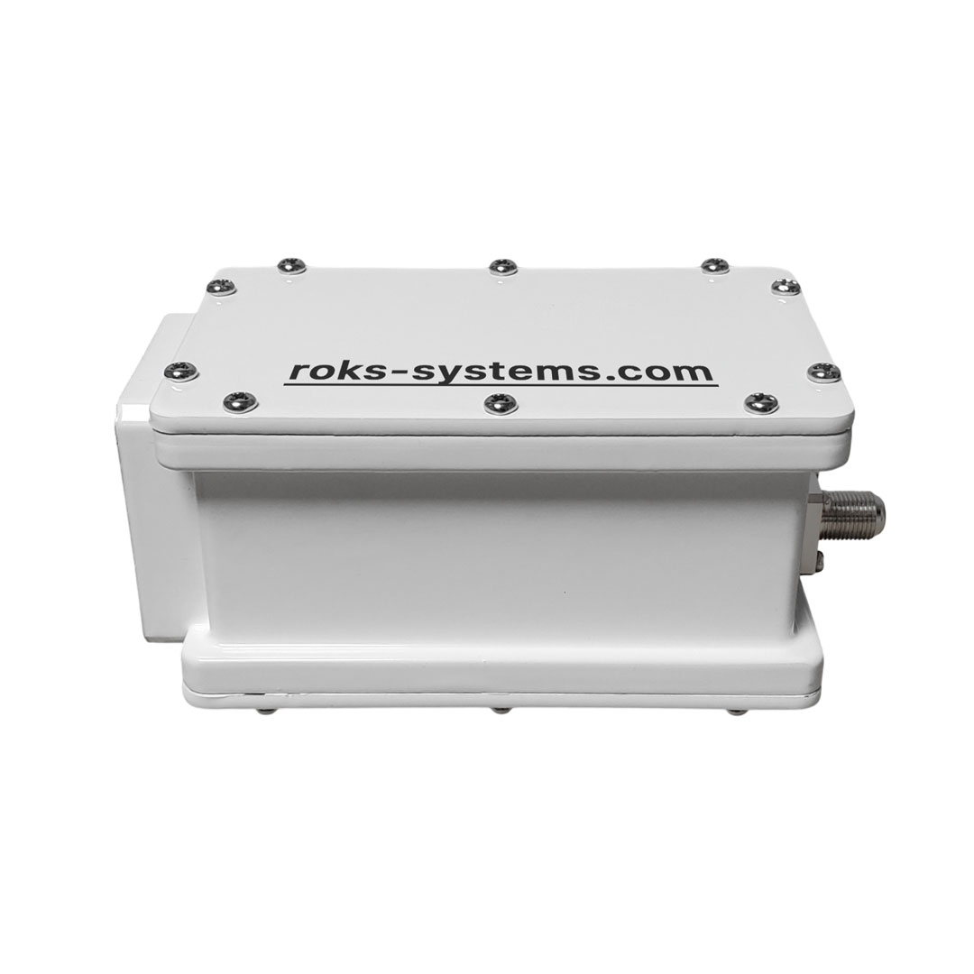
Dimensions: 70 x 59 x 118 mm
Weight: 620 g
⚙️ Main Functions:
Downconvert X-band RF to L-band IF for signal processing
Provide stable output with phase-locked loop oscillator
Maintain signal clarity with low phase noise and high image rejection
💡 Why Choose Us:
🧪 Own R&D lab with RF validation
🛡️ 1.5-year warranty + 7-year post-warranty support
💬 Dedicated telecom technical support
⚙️ High-reliability components for pro-grade systems
👉 Order today or reach out for a free consultation on integrating this LNB into your solution.
| Input parameters: |
| Input Frequency Range |
7.70 – 8.25 GHz |
| Input Waveguide Flange |
WR-112 (with groove) |
| Input VSWR, max |
2.5 : 1 |
| Local Oscillator: |
| LO Frequency |
6.75 GHz |
| LO Stability |
±5/10/25 kHz (internal reference) |
| Phase Noise @1 kHz |
–75 dBc/Hz |
| Phase Noise @10 kHz |
–80 dBc/Hz |
| Phase Noise @100 kHz |
–95 dBc/Hz |
| Output parameters: |
| Output Frequency Range |
950 – 1500 MHz |
| Output Connectors |
F-type or N-type female |
| Output VSWR, max |
2.5 : 1 |
| Output Power @P1dB |
+5 dBm min |
| Gain & Noise: |
| Noise Figure |
0.6 dB typ / 0.7 dB max |
| Conversion Gain |
60 dB typ (55–65 dB) |
| Gain Flatness |
4 dBp-p max |
| Gain Ripple at 36 MHz |
1 dBp-p max |
| Image Rejection |
≥ 40 dBc |
| Power & Mechanical: |
| Power Supply |
+12 to +24 VDC |
| Required Current |
300 mA max |
| Waterproof |
IP67 |
| Operating Temperature |
–40℃ to +60℃ |
| Dimensions |
70 x 59 x 118 mm |
| Weight |
620 g |