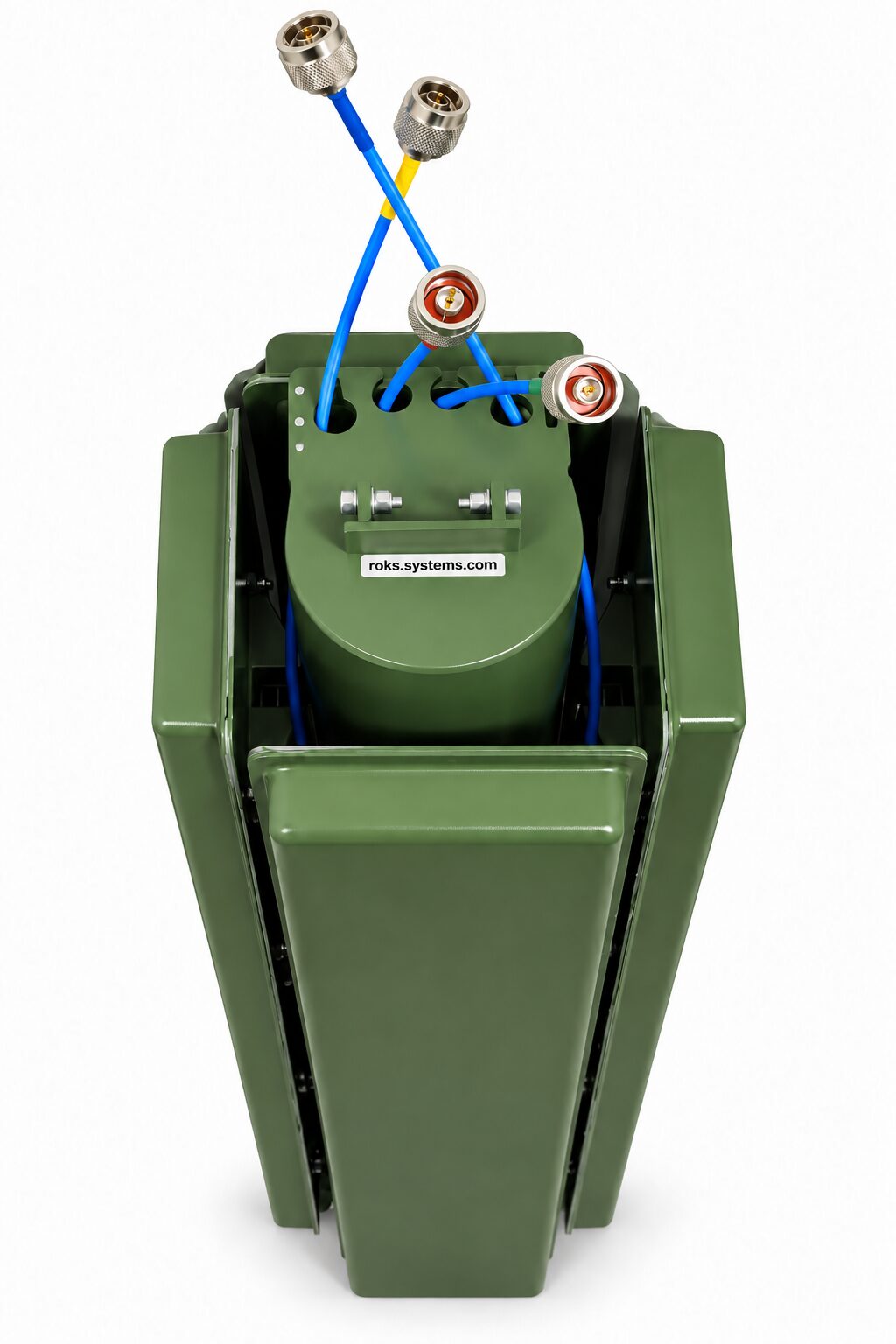
The P4SA012-06V1 4-Element Balanced Dipole Antenna Array is designed to receive radio waves across the 120-600 MHz frequency range and to support radio direction finding. Four spatially separated balanced dipoles are arranged at 90° to one another, allowing the system to determine signal direction from phase and amplitude differences between the received signals.
Each antenna element uses vertical linear polarization, 50 Ohm impedance, and a separate N-type male output. The dipoles are produced by photolithography on dielectric sheet material, installed inside radio-transparent housings, and mounted on a foldable support structure for practical deployment.
Detailed Description
The P4SA012-06V1 4-Element Balanced Dipole Antenna Array is a receiving antenna assembly designed for radio waves in the 120-600 MHz frequency range. Its primary purpose is to provide spatially separated signal reception for determining the direction of arrival of radio waves.
The assembly consists of four balanced dipole elements positioned at 90° to one another. The direction-finding method is based on comparing the phase and amplitude differences of the signals received by each antenna element.
Each balanced dipole has its own independent N-type male output, allowing the signals from the four antenna elements to be processed separately. The antenna operates with vertical linear polarization and has a specified impedance of 50 Ohm.
The antenna elements are manufactured using photolithography on dielectric sheet material. Each element is installed inside a radio-transparent housing, while the complete four-element assembly is mounted on a foldable support structure.
This configuration combines broad 120-600 MHz frequency coverage, four spatially separated receiving elements, individual RF outputs, and a deployable mechanical structure in a single direction-finding antenna assembly.
Key Features of the P4SA012-06V1 120-600 MHz Antenna Array
- Wide 120-600 MHz operating frequency range.
The P4SA012-06V1 antenna assembly is designed to receive radio waves throughout the specified 120 to 600 MHz frequency range.
- Four spatially separated balanced dipoles.
The system consists of four individual balanced dipole antennas, providing separate spatial sampling of the received radio signal.
- 90° antenna element arrangement.
The four antenna elements are positioned at 90° to one another, forming the specified spatial configuration of the antenna assembly.
- Designed for radio direction finding.
The assembly is intended to determine the direction of arrival of radio waves by evaluating differences in the phase and amplitude of signals received from the individual antennas.
- Independent RF output from each element.
Each of the four balanced dipoles has a separate N-type male connector, allowing each received signal to be accessed individually.
- Vertical linear polarization.
The antenna elements operate with vertical linear polarization throughout the specified operating frequency range.
- 50 Ohm impedance.
The specified RF impedance of the antenna elements is 50 Ohm.
- Defined gain characteristics.
Typical gain is -3.24 dBi at 150 MHz, 3.22 dBi at 300 MHz, 2.47 dBi at 550 MHz, and -0.954 dBi at 600 MHz.
- High cross-polarization isolation at specified frequencies.
Typical cross-polarization isolation is 53 dB at 150 MHz, 63 dB at 300 MHz, 40 dB at 550 MHz, and 39 dB at 600 MHz.
- Defined E-plane and H-plane radiation characteristics.
The specified -3 dB beamwidth varies with frequency. In the E-plane it is 80.1° at 150 MHz, 77° at 300 MHz, 39.3° at 550 MHz, and 36.3° at 600 MHz. In the H-plane it is 157.4°, 142.9°, 72.7°, and 89.5°, respectively.
- Photolithographic antenna construction.
The balanced dipoles are manufactured by photolithography on dielectric sheet material.
- Radio-transparent housings.
The antenna elements are installed inside radio-transparent protective housings.
- Foldable support structure.
The complete antenna array is mounted on a foldable supporting structure, providing the specified mechanical configuration for deployment.
- Wide operating temperature range.
The P4SA012-06V1 is specified for operation from -40 to +50 °C.
- Defined environmental operating conditions.
The specified operating atmospheric pressure is 750 ± 20 mmHg, while operating relative humidity is 90% at 25 °C.
Applications
The P4SA012-06V1 120-600 MHz antenna array is intended primarily for receiving and direction-finding applications.
- Radio direction finding.
The main application is determining the direction of arrival of radio waves across the specified 120-600 MHz frequency range.
- Phase-comparison direction finding.
Signals received by the four spatially separated antenna elements can be compared according to their phase differences.
- Amplitude-comparison direction finding.
The received signals can also be evaluated according to their amplitude differences as part of the stated direction-finding method.
- Wideband radio-wave reception.
The assembly can receive radio waves over the complete specified 120-600 MHz operating range.
Compatibility of the 4-Element Balanced Dipole Direction-Finding Antenna Array
The P4SA012-06V1 is intended for receiving and direction-finding systems covering 120-600 MHz and using vertical linear polarization, 50 Ohm impedance, and individual N-type male RF connections. Integration should support separate signal processing from all four antenna elements.
How It Works ❓
- Four-element signal reception.
The same incoming radio wave is received by four spatially separated balanced dipoles positioned at 90° to one another.
- Independent antenna outputs.
Each antenna element provides its received signal through a separate N-type male connector.
- Phase difference evaluation.
Because the antenna elements occupy different positions in space, the received signals can have different phases. These phase differences are used when determining the direction of arrival.
- Amplitude difference evaluation.
Differences in the received signal amplitudes between the four antennas also contribute to the stated direction-finding method.
- Direction-of-arrival determination.
By evaluating the phase and amplitude differences between signals from the four elements, the receiving system can determine the direction from which the radio wave arrives.
Why Choose the 4-Element Balanced Dipole 120-600 MHz Vertical Polarization❓
The P4SA012-06V1 combines 120-600 MHz frequency coverage, four spatially separated balanced dipoles, vertical linear polarization, 50 Ohm impedance, separate N-type male outputs, and a 90° element arrangement in one direction-finding antenna assembly. Its photolithographically manufactured antenna elements, radio-transparent housings, foldable support structure, and operation from -40 to +50 °C provide a defined configuration for radio-wave reception and direction-of-arrival determination based on phase and amplitude comparison.
Order on our website today – get your personal discount 🤝
Any questions? Ask our manager – we are always glad to help select the exact parameters according to your telecommunication needs 📞