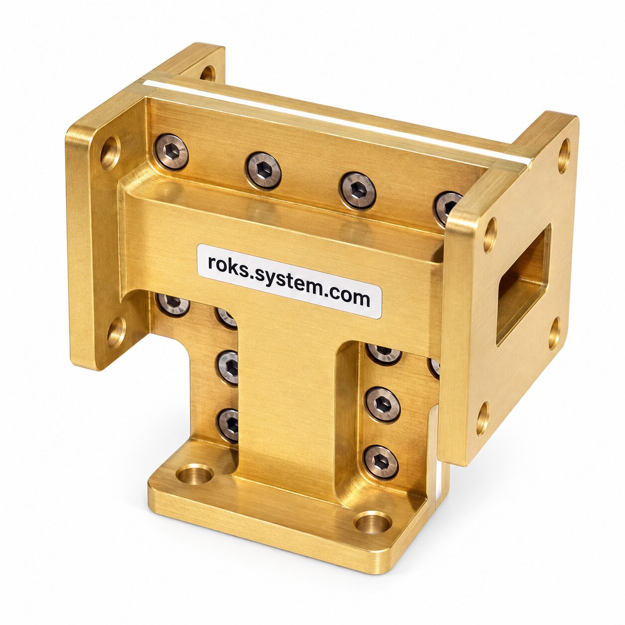
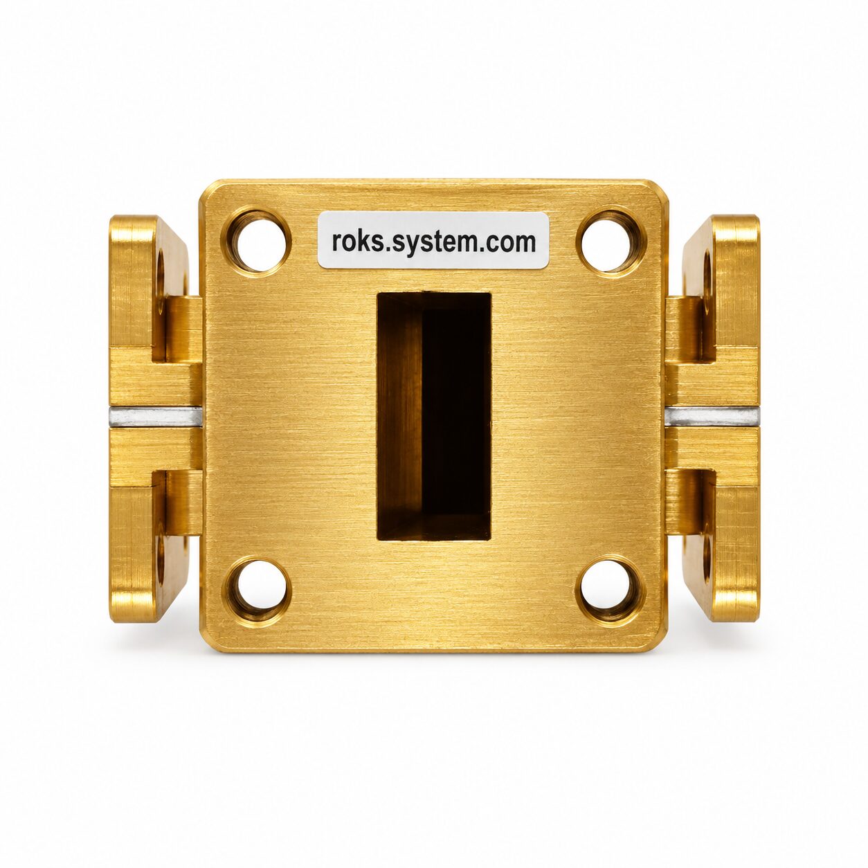
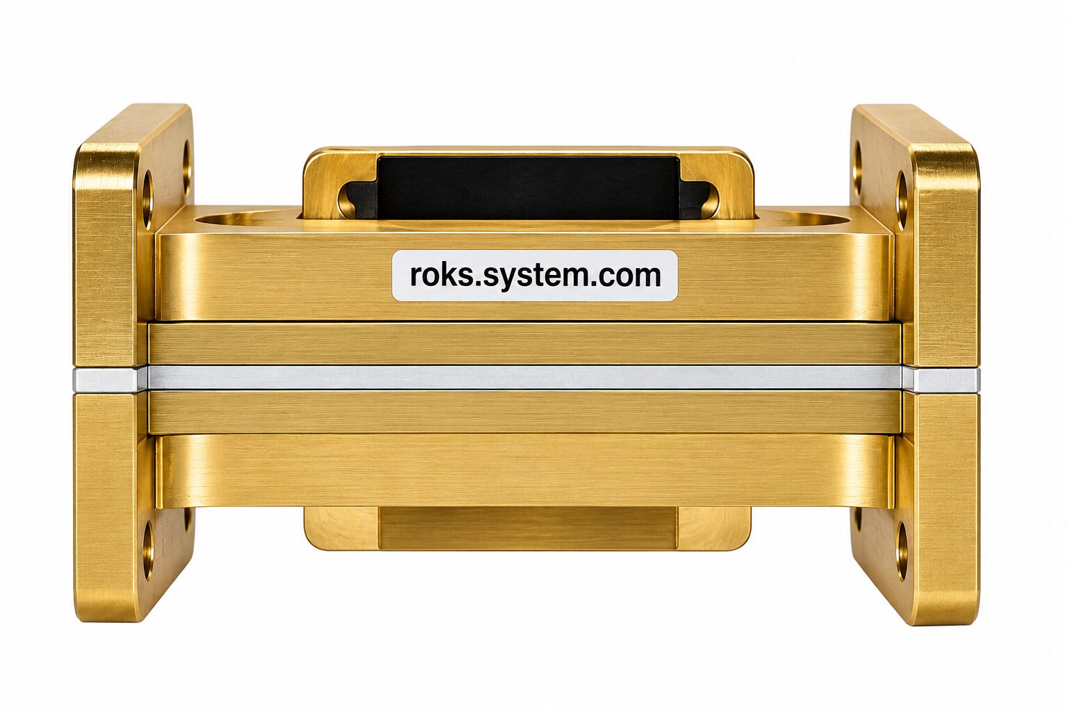
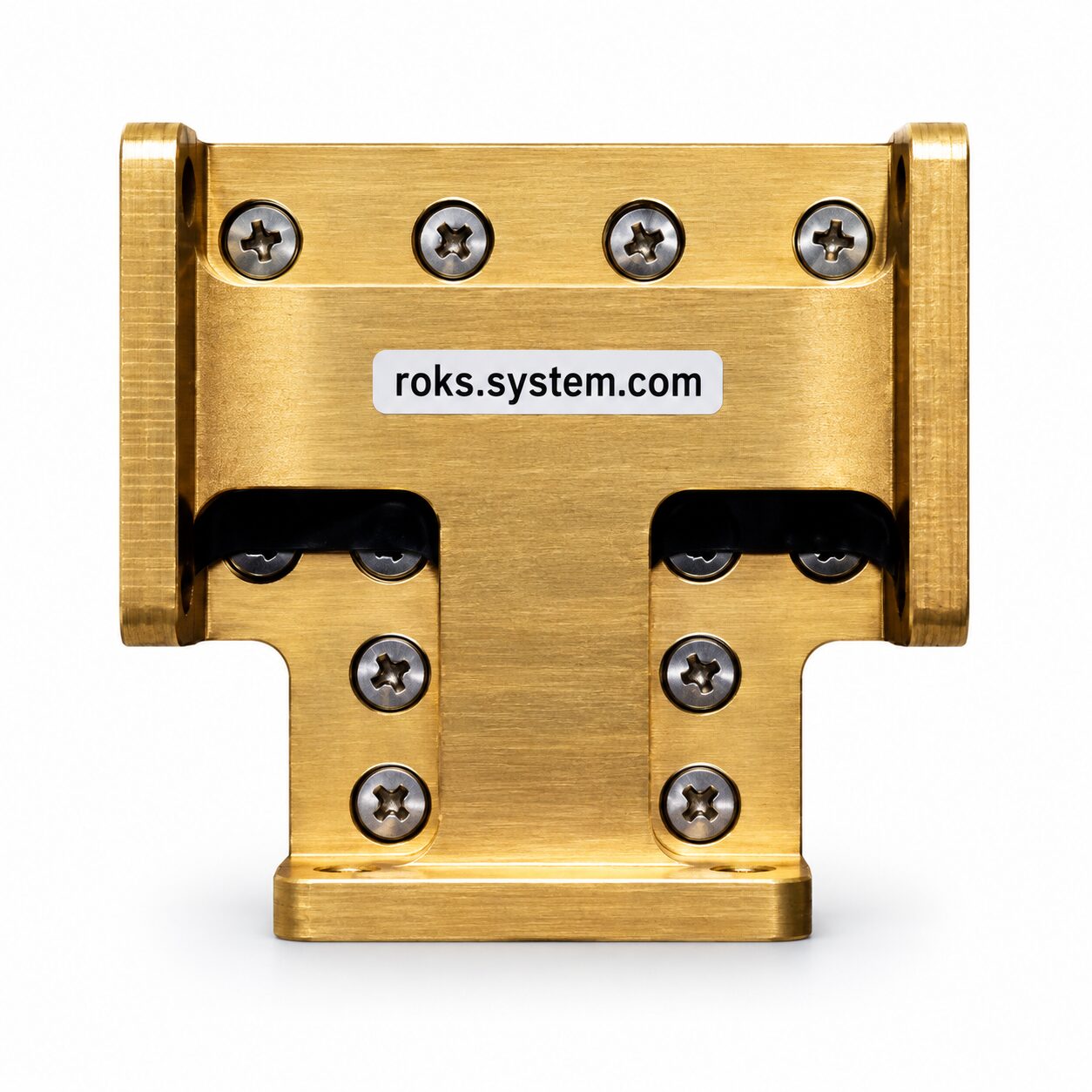
The Two-Way E-Plane Ku-Band Waveguide Power Divider is designed for SAT and VSAT systems that require equal division of a microwave signal between two branches. Its E-plane configuration performs 1:2 anti-phase power division and is intended for high-power waveguide applications. The specified insertion loss is 0.5 dB, with a return loss of -25 dB.
The divider provides 6-7 dB isolation between output ports and is suitable for Ku-band waveguide paths. Its passive waveguide design supports signal distribution in satellite communication and antenna feed systems where reliable two-way splitting, low transmission loss, port isolation, and high-power capability are required.
Detailed Description
The Two-Way E-Plane Ku-Band Waveguide Power Divider is a passive microwave component designed to divide a signal into two output branches. It is intended primarily for SAT and VSAT systems where reliable two-way signal distribution within a waveguide path is required.
The divider uses an E-plane configuration and performs 1:2 anti-phase power division. Its key RF parameters are an insertion loss of 0.5 dB, a return loss of -25 dB, and 6-7 dB isolation between output ports. These characteristics are specified on the current UMT product page.
An important advantage of this waveguide power divider is its suitability for high-power applications. No numerical maximum power rating is specified in the available data, so no unsupported power value is stated.
The component is intended for integration into Ku-band waveguide paths, including satellite communication and antenna feed systems requiring two-way RF signal distribution. UMT also identifies the divider for use in its antenna assemblies and Ku-band signal distribution applications.
Key Features of the Two-Way E-Plane Ku-Band Waveguide Power Divider
- Equal 1:2 signal division.
The waveguide power divider is designed to divide the incoming signal between two output branches, providing the required two-way distribution for SAT and VSAT RF paths.
- Anti-phase power division.
A key functional feature of the E-plane divider is anti-phase division, making it suitable for systems where this phase relationship between the divided signals is required.
- Low insertion loss of 0.5 dB.
The specified 0.5 dB insertion loss limits additional signal loss introduced by the power divider into the waveguide path.
- Return loss of -25 dB.
The specified -25 dB return loss is one of the main RF performance parameters of the divider.
- Isolation of 6-7 dB.
The specified isolation between output ports is 6-7 dB, defining the level of separation between the two branches.
- High-power capability.
The divider is intended for applications requiring operation with high RF power. Since an exact maximum power rating has not been provided, no numerical power value is specified.
- Passive waveguide design.
The device performs signal division directly within the waveguide path and does not require an active RF amplification stage for its dividing function.
Applications
The Two-Way E-Plane Ku-Band Waveguide Power Divider is primarily intended for SAT, VSAT, antenna feed, and microwave signal distribution systems.
- SAT communication systems.
The divider can be used where a Ku-band satellite RF signal must be divided between two waveguide branches.
- VSAT systems.
It is suitable for VSAT equipment and waveguide assemblies requiring two-way signal distribution.
- Antenna feed systems.
The divider can be integrated into waveguide feed networks where one signal path must be divided into two branches. The existing UMT implementation also uses this divider in an antenna sector assembly.
- Ku-band waveguide signal distribution.
The component is intended for Ku-band waveguide paths requiring equal two-way power division.
- High-power RF paths.
The divider is suitable for applications where the waveguide distribution component must withstand relatively high RF power.
Compatibility of the Two-Way E-Plane Waveguide Power Divider 0.5 dB Insertion Loss
The divider is intended for Ku-band waveguide paths and SAT/VSAT systems requiring 1:2 anti-phase signal division. Compatibility should be checked against the required waveguide interface and system configuration before ordering. The available data do not specify an exact waveguide size or numerical maximum power rating.
How It Works ❓
- Input signal distribution.
The incoming microwave signal enters the E-plane waveguide divider and is divided between two output branches.
- 1:2 power division.
The device provides equal two-way signal distribution for systems requiring one input path to feed two output paths.
- Anti-phase outputs.
The divided signals have the specified anti-phase relationship, which is a defining functional characteristic of this configuration.
- Low-loss waveguide transmission.
During division, the specified insertion loss is 0.5 dB, while the return loss is -25 dB and port isolation is 6-7 dB.
Why Choose the Two-Way E-Plane Ku-Band Waveguide Power Divider -25 dB Return Loss, 6-7 dB Isolation ❓
The Two-Way E-Plane Ku-Band Waveguide Power Divider combines equal 1:2 anti-phase signal division, 0.5 dB insertion loss, -25 dB return loss, 6-7 dB isolation, and high-power capability. This combination makes it a practical waveguide component for SAT and VSAT systems where reliable two-way Ku-band RF signal distribution is required.
Order on our website today — get your personal discount 🤝
Any questions? Ask our manager — we are always glad to help select the exact parameters according to your telecommunication needs 📞